


Electrical Safety in Hospitals: Electrocution & Fire due to Electrical Short Circuit
READ AS MAGAZINE PDF
ire in buildings due to an electrical short circuit has been common from the day of the invention of electricity. Statistics show a large number of accidents in buildings are from low voltage electricity. During the last two years, there were more than 25 incidents of fire which occurred in hospitals, mostly due to electrical installation. The consequences of these accidents are arching, flashovers, fires and shocks.
Electrical faults that result in the fire are believed to be caused by overloading, mediocre or nonstandard cables and insulations, ageing cables, defective sockets, damaged contacts, etc. These assumptions, however, are general in nature for a normal electrical installation but are inapplicable to a good and reliable installation due to;
- Fuses, MCBs, and other protective devices are used in electrical installations. These safety measures are designed to cut off the supply during overloading to prevent an accident. In the real world, the conclusion should read “fire is due to non-disconnection / non-operation of the protective device” instead of “fire is due to overloading”.
- The code of practice and regulations includes periodic testing and verification of new installations to make sure the electrical installation is in good working order. These tests should be performed regularly to detect potential degradations, such as loose contacts in wiring. Lack of a high-quality, routinely-tested electrical installation where degradations are corrected well in advance is the real cause of accidents, not poor quality/ nonstandard cables or ageing cables.
This article aims to introduce the most modern electrical safety measures that can void the generalised reason for accidents in hospitals.
Electrical Safety in Hospitals
In this article, the safety scenarios are classified into three steps:
- Shock protection in the patient environment such as group 1 or group 2 medical locations. (Ref IS17512: 2021 or IEC 60364-7-710).
- Shock protection in General locations (Ref IS732 /IEC 60364- 1 to 6)
- Safety services.
Medical locations are classified into Group 0, Group 1 and Group 2.
Group 0 is a medical location where medical electrical equipment can be brought into contact with the patient or needs to be touched by the patient or a medical location where ME equipment or ME systems are not intended to be used.
Group 1 is a location where medical electrical equipment is used externally (applied parts are used externally).
Group 2 is a location where medical electrical equipment is used in applications such as intracardiac procedures, operating theatres, and necessary treatment where discontinuity of the supply can cause danger to life. An intracardiac procedure is a procedure whereby an electrical conductor is placed within the heart of a patient or is likely to come into contact with the heart, such conductors being accessible outside the patient’s body. In this context, an electrical conductor includes insulated wires such as cardiac pacing electrodes or intracardiac ECG electrodes, or insulated tubes filled with conducting fluids. The following terms and definitions are also to be noted.
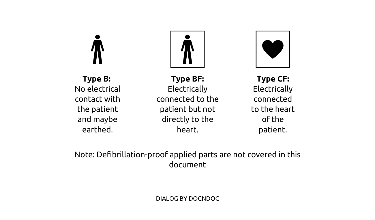
Applied Part: Part of the medical electrical equipment which in normal use comes into physical contact with the patient for the equipment to perform its function, or can be brought into contact with the patient, or needs to be touched by the patient. They are classified into Type B, Type BF, and Type CF
Medical Electrical Equipment (ME equipment): Electrical equipment having an applied part or transferring energy to or from the patient or detecting such energy transfer to or from the patient and which is provided with not more than one connection to a particular supply main and intended by its manufacturer to be used in the diagnosis, treatment, or monitoring of a patient, or for compensation or alleviation of disease, injury or disability.
Medical Electrical system (ME system): Combination of equipment, at least one of which is ME equipment to be interconnected by functional connection or by use of a multiple socket outlet.
Protective Equipotential Bonding: Electrical Bonding of various metal parts to reduce potential differences between two simultaneously accessible metallic parts. It is divided into main protective equipotential bonding (main bonding) and Supplementary protective equipotential bonding (Supplementary bonding).
Safety measures for the patient environment
Group 1 and Group 2 medical locations are places where applied parts of the ME equipment are extensively used. Any potential difference between faulty applied parts could endanger the patient. The application of medical electrical equipment may introduce hazards due to several reasons as follows:
- A device’s inability to carry out its intended function (such as a lung ventilator failing to keep the patient ventilated) or an error in function (e.g. Excessive drug delivery by an infusion pump, or excessive temperature in a baby incubator).
- Energies (e.g in the form of electrical or thermal) are delivered when functioning normally, e.g.(1) leakage current or functional current flowing from a cardiac defibrillator or high-frequency surgical equipment unit through unintended pathways in the patient or operator (2) exposure to radiation of an unintended part of the patient or operator (3) exposure of the patient or operator to ultrasonic energy or accelerated elementary particles (4) excessive heating or cooling of the patient.
- Equipment faults, (e.g. fire, electric shock, explosion, expelled parts, excessive ionizing or non-ionizing radiation resulting from equipment malfunction, leakage or over-exposure, excessive temperatures of accessible surfaces leading to burns).
- Fire or explosion resulting from ignition of flammable material within the vicinity of the ME equipment.
- Mechanical failures in normal and fault conditions. incorrect installation of ME equipment, e.g. Inadequate earthing of class-1 ME equipment.
- Incorrect selection and use of ME equipment, (e.g. The use of ME equipment having a type bf or type b applied part to carry out an intracardiac procedure, Selection of an incorrect energy scale while using an internal cardiac defibrillator).
- Electromagnetic interference, (e.g. Interference of an ECG display by high-frequency surgical equipment, generation of interference with adjacent medical electrical equipment by strong magnetic fields emanating from a display).
- Release of corrosive, poisonous or hot liquids or gases, or contact with biologically unsafe materials.
- Disposal of material and by-products resulting from the use of medical electrical equipment, (e.g. The disposal of radioactive substances used in nuclear medicine).
Selection of ME equipment
The first thing a user must do is make sure the equipment they are using satisfies the fundamental safety and performance standards for ME equipment.
Medical electrical equipment Particular requirements: Basic safety and essential performance
- ISO 80601-2-12 – Critical care ventilators
- ISO 80601-2-84 – Ventilators for the emergency medical services environment
- ISO 80601-2-79 – Ventilatory support equipment for ventilatory impairment
- ISO 80601-2-87 – High-frequency ventilators
- ISO 80601-2-84 – Ventilators for the emergency medical services environment
- ISO 80601-2-80 – Ventilatory support equipment for ventilatory insufficiency
- ISO 80601-2-72 – Home healthcare environment ventilators for ventilator-dependent patients
Note: There are hundreds of ISO standards that exist on ME equipment and system, which is not the focus of this article.
Installation of ME equipment
- The location where the ME equipment is installed shall satisfy special requirements such as:
- Additional protective bonding and protective devices to restrict continuous voltage differences.
- Restriction of voltage differences by supplementary equipotential bonding (e.g. a fault voltage of < 25 volts in group 2 locations). During the application of equipment with direct contact with the patient, at least a potential equalized zone around the patient shall be provided with a patient centre bonding bar to which the protective and functional earth conductors of the equipment are connected. All accessible extraneous conductive parts in the zone shall be connected to this potential equalization bar.
- Restriction of the potential equalization zone to the zone around one patient, meaning practically around one operation table or one bed in an intensive care room.
- If more than one patient is present in an area, the connection of the various potential equalization centres to a central potential equalization busbar should preferably be connected to the protective earth system of the power supply. In its completed form the equipotential bonding network may consist partly of fixed and permanently installed bonding and part of several separate bonding which are made when the equipment is set up near the patient.
- The necessary terminals for these bonding connections should be present on the equipment and in the installation.
- Restriction of the duration of transient voltage difference by the application of SPDs.
- Continuity of power supply to certain equipment in the case of a first insulation fault to earth and restriction by electrical separation.
- Monitoring of the first insulation fault to earth in a medical IT system.
- Prevention of ignitions and fire in rooms where flammable anaesthetics or flammable cleaning or disinfection agents are used by ventilation, anti-static precautions and careful layout of the installation.
- Safety supply system for major parts of the hospital, usually a DG and or a UPS and essential circuits to be connected to it.
- Special and uninterrupted safety supply system for critical equipment such as life-supporting equipment and operating room lamps.
- Suppression of electromagnetic interference by the layout of the building and wiring and provision of screening arrangements. Limits for magnetic fields of main frequency are necessary for several sensor measurements.
Electrical installation in general locations of a hospital
- TN-S power supply.
- An efficient “protective equipotential bonding and automatic disconnection of supply” ensures fault voltage of less than 50 VAC and disconnection time < 0.4 seconds at the final circuits up to 63 amps.
- Overvoltage control for the safety of the equipment.
- Electrical installation of Overvoltage category III and IV at a fixed part of the installation, Category II for all connected equipment.
- Electrical equipment of overvoltage category I shall not be connected to the power supply from the transformer.
- Protective conductor currents are limited to a few mA.
- Effective shielding and cable routing measures.
- All circuits’ efficiency of automatic disconnection and continuity of conductors were tested to avoid loose contacts and overheating.
- Insulation resistance of the complete installation, satisfying the safety standards.
Equipment in Hospitals requires special care for the power supply impedance (e.g X-ray machine)
A conventional X-ray unit uses high power during Radiography. The power used during this time will be multiple times the power consumed during standby mode; however, it is for a short time of a few mS. Some applications also used a burst of exposure which may exist for a few seconds. The selection of a protective device (such as Fuse / MCB) and the input impedance of the supply system shall meet the requirements of safety and short-time requirements of high power. E.g. for a high-power 3-phase X-ray machine, the input impedance between phases shall be up to 100 mΩ. These requirements shall be fulfilled by testing as the best practice and if possible, by periodic testing.
Fundamental mistakes in Hospitals leading to accidents
L.V. electrical supply falls under the TN-S, TN-C-S, TT, IT, etc. categories. In these networks, safety is achieved by automatically cutting off the supply (except for IT), but how this is done varies between networks. Unfortunately, system earthing is commonly disregarded or incorrectly performed in hospitals.
Code of practices of the Bureau of Indian Standards such as IS 3043 and IS 732 clearly explains the methods for disconnecting the supply during earth fault:
- The characteristics of protective devices and the cross-sectional area of the conductor shall be so chosen that if a fault of negligible impedance occurs anywhere between the phase conductor or exposed conductive part and protective conductor, automatic disconnection of the supply will occur within a possible minimum time.
- The fault loop impedance has to be low enough to allow adequate fault current to flow to cause an overcurrent protective device (for example, a fuse or circuit breaker) in the faulty circuit to operate in a sufficiently short time.
- In general, every circuit is provided with a means of overcurrent protection. If the fault loop impedance is low enough to cause these devices to operate within the specified times (that is, sufficient current can flow under fault conditions), such devices may be relied upon to give the requisite automatic disconnection of supply.
Hence, Fault Loop Impedance is the deciding factor. Low fault loop impedance ensures a higher fault current which, in turn, trips the protective device within the specific time during a fault.
Fault loop impedance and its measurements are an unknown subject in India. Due to that, wrong protective devices are used, resulting in the non-functioning of the protective device during a short circuit, resulting in fire.
Using power from DG is common in India. Fault loop impedance testing while running the facility from different sources shows that the protective device is not tripping while running in DG. This means when the building runs in DG, Line to Neutral short circuits can cause a fire. Conventional Protective devices such as RCD are ineffective.
Testing, Initial and Periodic
The reliability of every electrical installation is assured by initial and periodic verification (inspection and testing). Globally the IEC 60364-6 sets the benchmark of verification. This has been adopted in IS732:2019.
The mandatory requirement in Govt of India safety regulations
The upcoming electrical safety regulations of the Govt of India have been included in Regulation 38. Provisions for supply and use of electricity in multi-storeyed buildings more than 15 metres in height.
Sub regulation (4) The owner or occupier of a multi-storeyed building shall ensure that electrical installations and works inside the building are carried out and maintained in such a manner as to prevent danger due to shock and fire hazards, and the installation is carried out in accordance with IS732 and National electrical code (SP30). Provided that hospitals and medical establishments shall have safety measures as per the National Electrical Code irrespective of height.
Sub regulation (8) Electrical Safety Verification of the installation shall be done as per IS 732.
Circulars from Govt of India to State governments to ensure electrical safety in hospitals
Due to the fire accidents in hospitals during Covid-19, Govt of India. Ministry of home affairs sent circulars to all state governments to ensure safety in hospitals.
Punishment under The Electricity Act 2003
Any violation or noncompliance to the safety regulations by the Govt of India, The electricity Act 2003 recommends 3 months imprisonment for the owner of the electrical installation (including directors/proprietors of a company who owns the facility). An additional 1 lac fine per accident and an additional fine of Rs. 5000 per day for continuing the failure are the provisions included in the Act.
List of Verification in General locations of a Hospital:
The following subjects are to be verified in general locations.
Verification:
To keep the power distribution system safe, it is necessary to accurately and timely diagnose various sensitive matters such as short circuits and other possible electrical faults. To ensure safety, various protection systems mentioned below should be integrated with the power distribution system and care should be taken by the Hospital Management to undertake periodic checking thereof as per IS 732:2019 and IS 17512:2021 to ensure that they are in good condition.
The following subjects are to be inspected (refer to IS732 clause 6.2.2.3).
The respective clause of IS732 against each inspection is referred to in the bracket.
- method of protection against electric shock (see 4.2);
- presence of fire barriers and other precautions against the propagation of fire and protection against thermal effects (see 4.3 and 5.2.7);
- selection of conductors for current-carrying capacity and voltage drop (see 4.3, 5.2.3 and 5.2.5);
- choice and setting of protective and monitoring devices (see 5.3);
- selection, location and installation of suitable overvoltage protective devices, where specified
- presence and correct location of suitable isolating and switching devices (see 5.3.6);
- selection of equipment and protective measures appropriate to external influences (see 4.3.2, 5.1.2.2 and 5.2);
- neutral and protective conductors correctly identified (see 5.1.4.3);
- single-pole switching devices connected in the line conductors (see 5.3.6);
- presence of diagrams, warning notices or other similar information (see 5.1.4.5);
- identification of circuits, overcurrent protective devices, switches, terminals, etc. (see 5.1.4);
- adequacy of connection of conductors (see 5.2.6);
- presence and adequacy of protective conductors, including main and supplementary equipotential bonding conductors (see 5.4);
- accessibility of equipment for the convenience of operation, identification and maintenance (see 5.1.3 and 5.1.4).
- measures against electromagnetic disturbances
The following tests are to be carried out. (Refer to IS732 clause 6.2.3.1)
- Resistance measurement of conductors and comparison
- Insulation resistance
- Insulation resistance ELV or electrical separation
- Floor and wall resistance/impedance
- Polarity test
- Effectiveness of automatic disconnection of supply
- Effectiveness of additional protection
- Phase sequence
- Functional tests
- Voltage drop.
The following additional tests (a to f) shall be carried out by the Hospital Management for every group 0, group 1 and group 2 medical location.
- Functional test of insulation monitoring devices of medical IT systems and acoustical/visual alarm systems. (annually)
- Measurements to verify whether the supplementary equipotential bonding is efficient or not. (Once in 2 years).
- Verification of the integrity of the facilities required with Supplementary equipotential bonding for equipotential bonding (once in 2 years).
- Verification of the integrity of the safety services. (monthly)
- Measurements of leakage current of the output circuit and the enclosure of medical IT transformers in no-load condition (once in 2 years).
- Checking of the tripping of RCDs at IΔn: not more than 12 months.
Bibliography:
- IEC 60513: Fundamental aspects of safety standards for medical electrical equipment
- IS 13450 (Part 1):2018 (IEC 60601-1: 2012): Medical Electrical Equipment, Part 1 General Requirements for Basic Safety and Essential Performance
- SP 30:2011 – National Electrical Code of India
- IS 732: Code of the practice of electrical wiring
- IS17512: Requirements for Electrical Installations in Medical Locations